¶ Profiles viewer
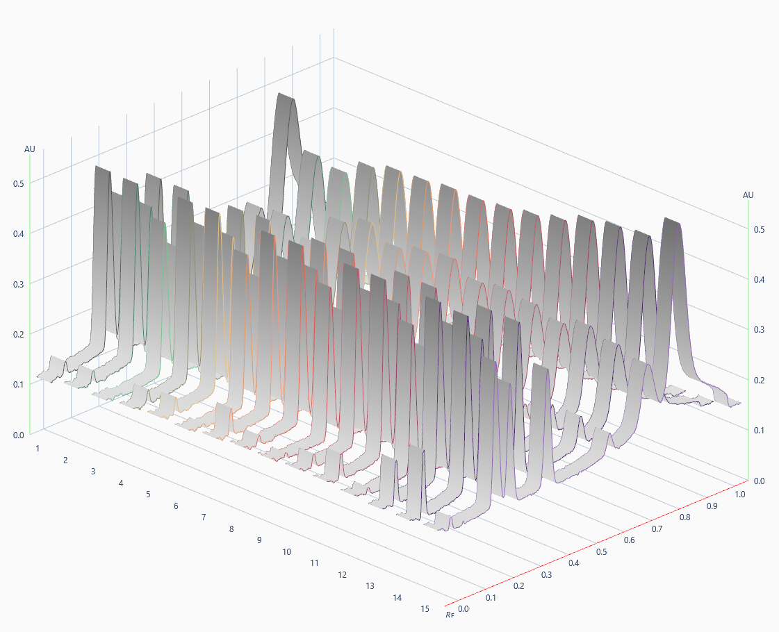
Profiles, either from TLC Scanner 4 or TLC Visualizer data, are displayed in several places in the analysis file, either in 2D view or in 3D view.
Note
In some cases, the view is blocked in 2D, several functionalities are then unavailable
The viewer is visible in:
Tracks View (limited to 2D)
Spectrum Positioning (limited to 2D)
Scanner Manual Control
Warning
The Profiles viewer needs DirectX 11, therefore it will not work on a PC having its accelerated graphics disabled or during a Remote Desktop session. You will see the error “3D view not available on this system or on Remote Desktop session” in these cases.
¶ Axis
Red axis: 𝑅ꜰ axis showing the profile from application to front
Green axis: AU axis
Track number axis (only in 3D)
¶ Navigation in 2D
¶ Zooming the view
Zooming in and out of the view is done with the mouse wheel

.
Alternatively, the keys

/

can be used.
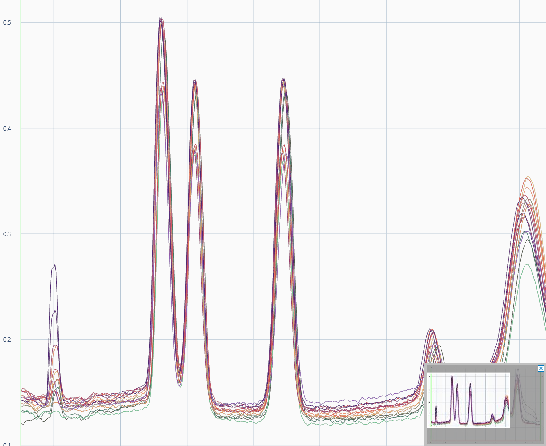
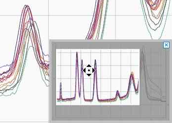
The navigation preview will be displayed on the bottom right corner of the viewer, the not grayed out part being what is currently displayed in the viewer. When Zooming Out, the preview disappears if the ratio reaches 1:1. The zoom can also be reset by clicking on

.
Note
Rotating isn’t possible in zoom mode.
¶ One axis zooming
It is possible to zoom in one axis horizontally or vertically. Horizontally, use the mouse wheel
while pressing

. Vertically, use the mouse wheel
while pressing

.
Alternatively, the keys
/
can be used.

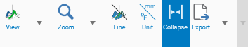
The zoom functions are also available from the toolbar.

Zoom in

Zoom out

Vertical zoom

Horizontal zoom
¶ Panning the view
Note
Panning is only possible in zoom mode.
Panning is done by pressing and holding

and dragging

.
Alternatively, the visible area in the overview can be dragged while holding

.
Step panning can be done with the keys:


¶ Navigation in 3D
¶ Zooming the view
See above Zooming the view.
¶ Panning the view
See above Panning the view.
¶ Rotating the view
Rotation is done by dragging the mouse with
.
Alternatively, you can press and hold

while dragging
.
Step rotation (15 °) can be done with the keys:

/
going down

/
going left

/
going right

/
going up

Some view presets can be selected this menu

profile: the 2D view
Isometric view

Dimetric from side view

Dimetric from top view

oblique: the profiles are parallel, good for comparison

top: like an image of the plate
Note
Isometric projection is a method for visually representing three-dimensional objects in two dimensions in technical and engineering drawings. It is an axonometric projection in which the three coordinate axes appear equally foreshortened and the angles between any two of them are 120 degrees
In dimetric projection, the direction of viewing is such that two of the three axes of space appear equally foreshortened, of which the attendant scale and angles of presentation are determined according to the angle of viewing; the scale of the third direction (vertical) is determined separately
¶ Viewing modes

toggle between line only and band display of the profiles

toggle between 𝑅ꜰ and mm unit for scale

toggle between collapsing or not the space of the hidden tracks
¶ Export
Several export are available:
Export to image: the current view is exported in an image file.
